
Introduction
As we promised before, we are entering a series of posts on how to create IoT solutions. But what we should create and which hardware should be chosen? After a certain brainstorming on what would be the best to get familiar with the world of IoT, we came to the conclusion that we would use Arduino Starter kit since this is a cost-effective hardware stack having great software solutions that help to record, read, and store data.
Another important positive aspect of this kit is that it’s used in the education process in Universities. So if you study at a technical University and don’t have your own kit, you can loan one for sure.

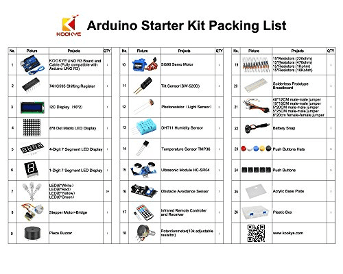
1. Arduino starter kit
Hardware is already selected, now we should think on what would we like to create? Let’s see what hardware we have in addition to our Arduino kit.
A list of available sensors is interesting to bring me a lot of ideas. But the first IoT solution should be easy to understand from the business and technical viewpoints. So Let’s take temperature sensor and measure temperature in many places, for instance in school and provide a dashboard with statistic.The Idea is simple, so let’s try to implement it.
1.1 Selecting hardware
Here is a list of our hardware:
- Arduino UNO R3
- Temperature Sensor TMP36
- Solderless Prototype Breadboard
- Three 25cm male-male jumper
Also, you will need to install Arduino Studio to write, compile and upload a program to the microcontroller.
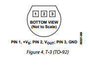
It seems everything is available and we can start creating our IoT solution, but where should we start from? What should we do first? My proposition is to get familiar with your sensor, so read the datasheet.
After learning the general information I can see that TMP36 is the low-voltage, precision centigrade temperature sensors. They provide a voltage output that is linearly proportional to the Celsius (centigrade) temperature. The TMP36 do not require any external calibration to provide typical accuracies of ±1°C at +25°C and ±2°C over the −40°C to +125°C temperature range. Our sensor is intended for a single-supply operation from 2.7 V to 5.5 V maximum. The TMP35 reads temperatures from 10°C to 125°C, is specified from −40°C to +125°C, provides a 750 mV output at 25°C, and operates to 125°C from a single 2.7 V supply. TMP36 have an output scale factor of 10 mV/°C.
Now we understand that output of our sensor is in mV and if we have 750mV it means that it’s 25°C and if it’s 800mV then it’s 30°C, but how to read this mV? Arduino has analog pins with logic for an analog/digital conversion, so using these pins we can read and interpret analog signals.
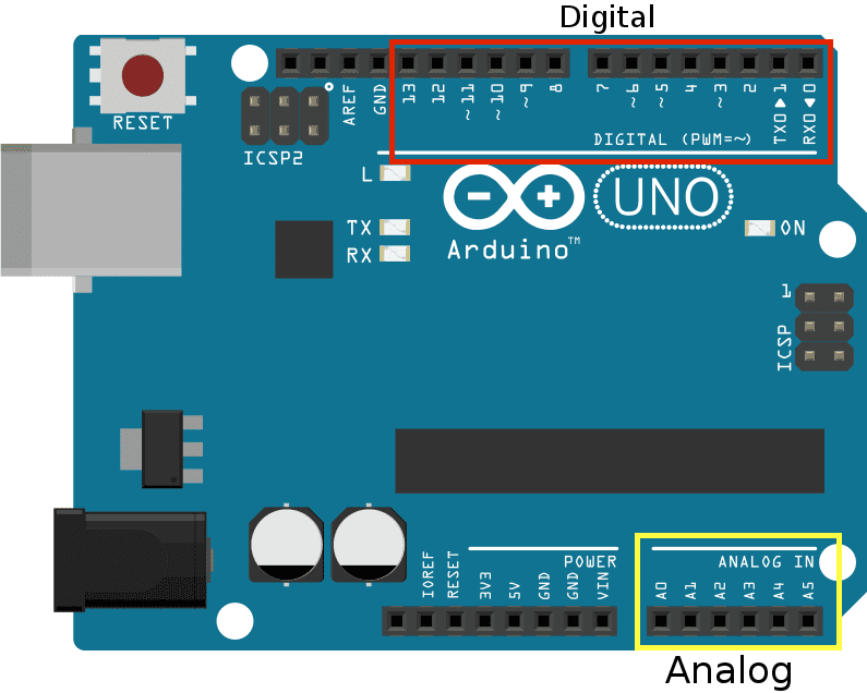
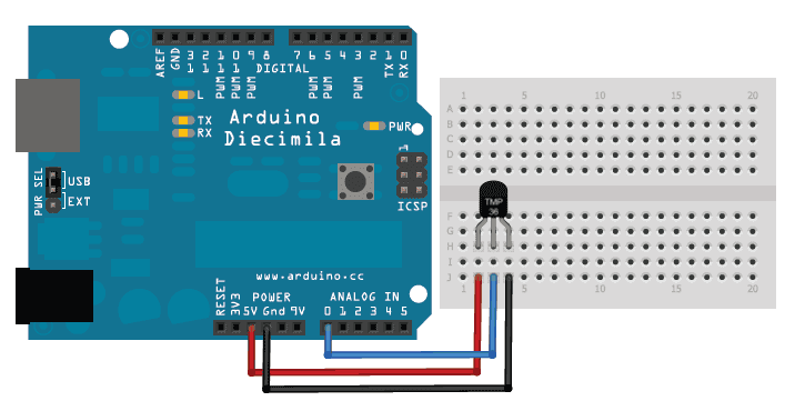
Arduino Studio by default has a list of functions that implement functionality for such features as reading from analog input. In our case, we need analogRead(pin). Let’s try to connect a sensor to our Arduino board, but which pin on sensor should be connected to which pin on board? Sensor GND should be connected to board GND, Vdd should be connected to 5V and OUT should be connected to any on analog pins. Here you can see the visualization of how to connect the sensor to a board.
2. Writing code
Now let’s run Arduino studio and try to write some code. Read the value from the specified analog pin. The Arduino board contains a 6 channel, 10-bit analog to digital converter. It means that it will map input voltages between 0 and 5 volts into integer values between 0 and 1023. This yields a resolution between readings of: 5 volts / 1024 units or, .0049 volts (4.9 mV) per unit.
float temp;

float volt;

float data;

static float static_volts_25degree = 0.75; //for 25 degrees we have 750mV

static float static_degrees = 25; //this is temperature for when we have 750mV

static float degree_step = 0.01; // 1 deg C step has 10mV

static float volts_per_unit = 0.0048828125; // 5/1024


void setup() {

Serial.begin(57600); //starting serial port with needed bound rate in bits per second

};


void loop () {

  data = analogRead(0); //analog pin with id 0

  volt = data*volts_per_unit - static_volts_25degree; //finding diff temperature for 25 degrees

  temp = static_degrees + volt / degree_step; // adding calculated diff temperature to our statically known temperature of 25 when we have 750mV


  Serial.println(temp);//writing value to serial port

  delay(500); // delay to not flood serial port

};
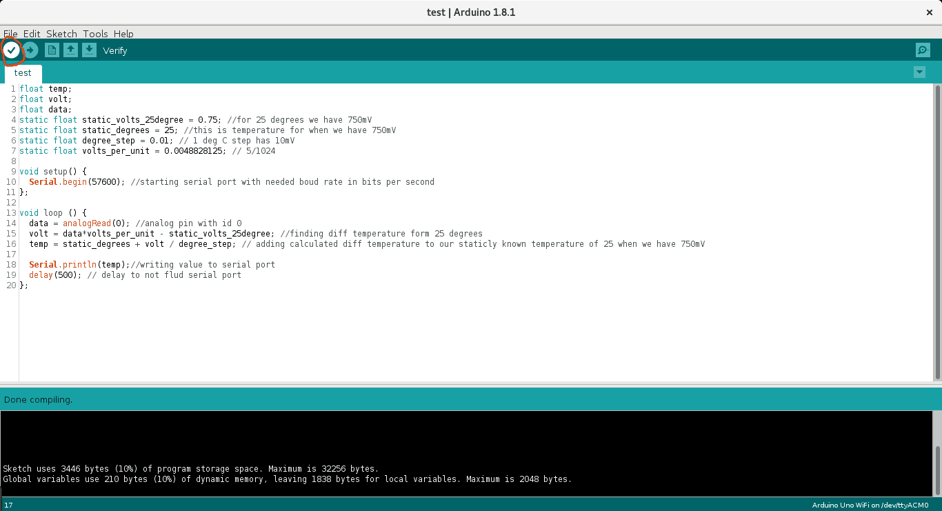
Copy and paste this code and press Verify to check if everything is ok. You should see “Done compiling”, another way you will see a message with an error.
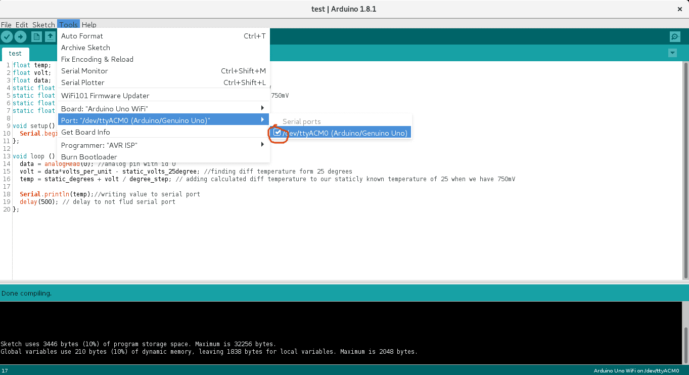
Now connect your Arduino UNO to your computer with USB cable and select your device in settings.
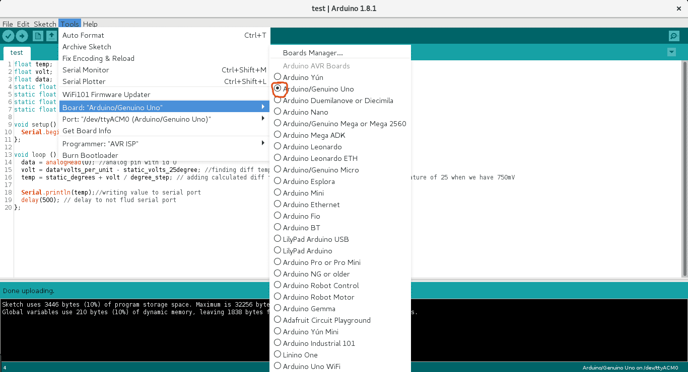
Please check your Arduino. Otherwise, you won’t be able to upload the compiled code and go to Board and select your board type:
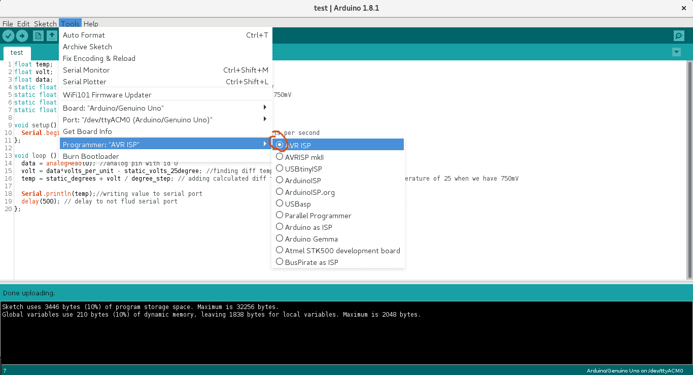
And select programmer app that will upload the compiled code to Arduino.
Finally, you are ready to upload the compiled program to a microcontroller.
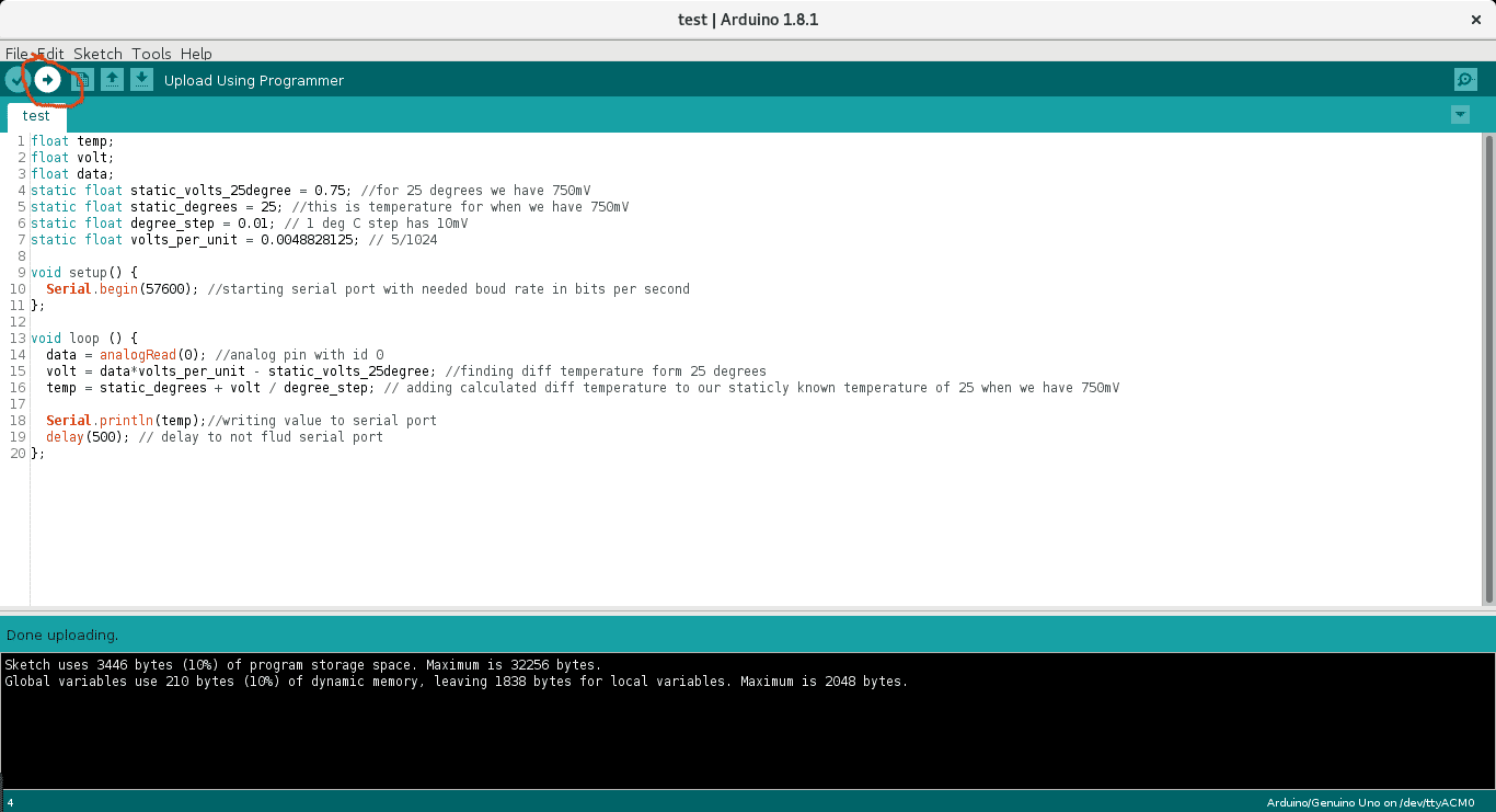
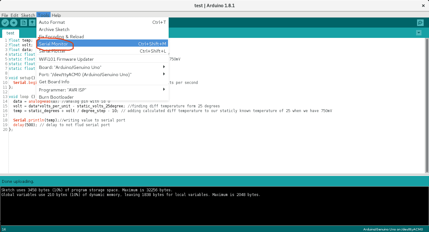
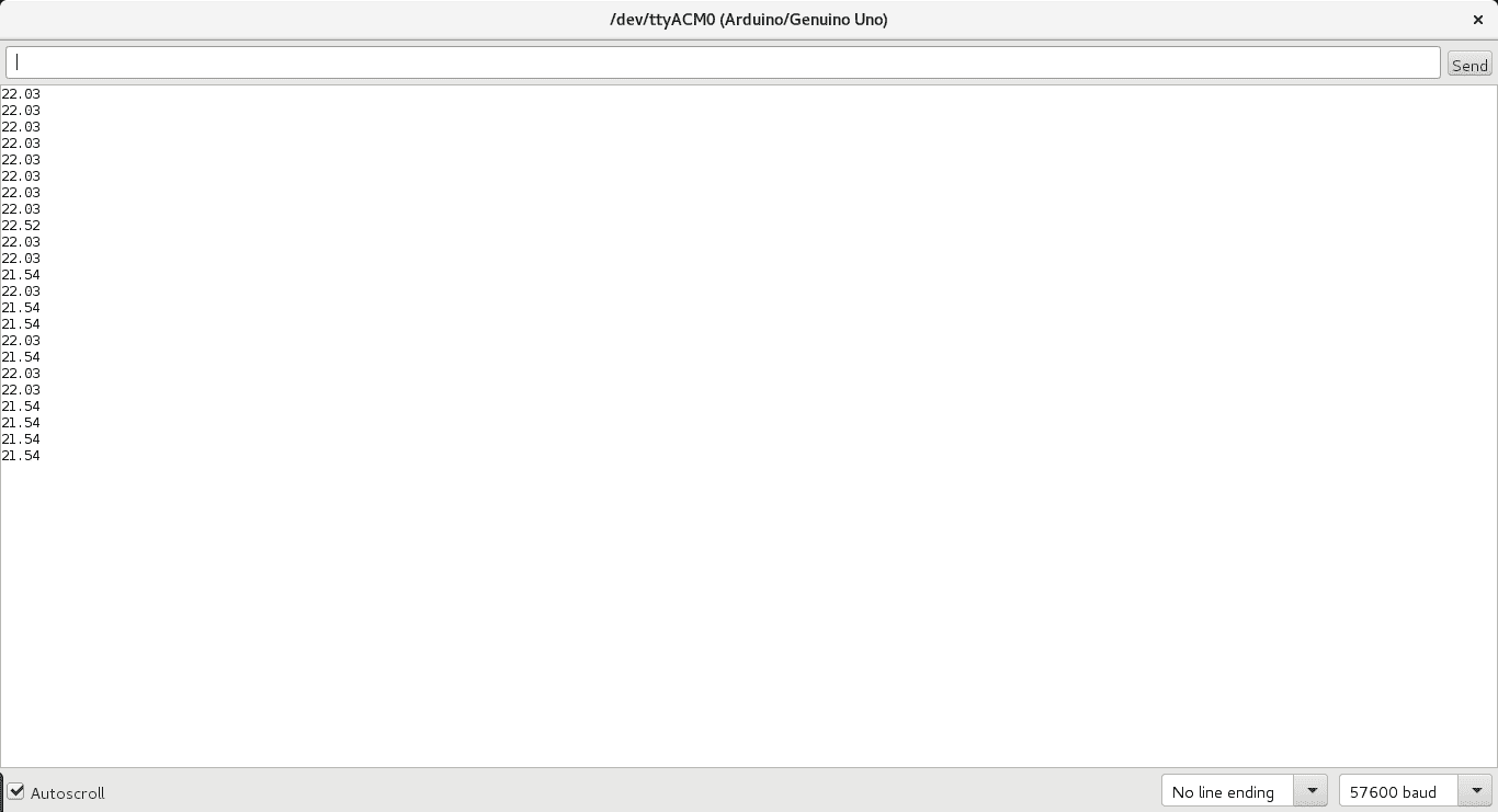
After you see “Done Upload” you can open serial monitor to see results.
Conclusion
Next time we will create an application for desktop (Mac, Window or Linux) that reads data from Arduino and sends data to Predix cloud. If you don’t know what Prefix is and how to work with it, you should check our previous article https://indeema.com/blog/how-to-code-iot-with-ge-predix-beginning.
Yo can find the code here: https://github.com/IndeemaSoftware/IoT-temperature-with-Predix-and-Qt/tree/master/Adruino
We hope that you take this article useful in order to create more complex IoT solution shortly.

