


Hardware engineering / UAV flight stack
Flight controller and electronic speed controller (ESC) PCBsRequirements, schematic and PCB design, board bring-up
Flight-controller and ESC electronics for a 7-inch drone flight stack
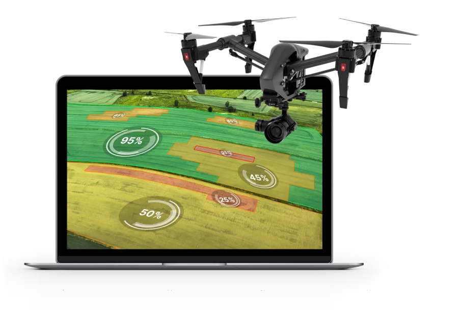
A drone company had a concept for a lightweight 7-inch drone intended for work such as crop monitoring, wildlife observation and land surveying. Beyond the idea of a custom flight stack, it had no tangible assets: no requirements, schematics, boards or prototypes.
Design flight-controller and electronic speed controller boards that form one matched flight stack, stay compatible with widely used open-source firmware (Betaflight on the flight controller, BLHeli on the ESC) and can be built by a contract manufacturer.
- Product
- Flight controller and electronic speed controller (ESC) PCBs
- Buyer
- Drone product teams with a vehicle concept but no flight-control electronics of their own
- Engagement
- Requirements, schematic and PCB design, board bring-up
- Indeema scope
- Requirements and specification, Early hardware prototyping, Schematic design, PCB layout and production files, Bring-up and revision
The product need
What had to become possible
Design flight-controller and electronic speed controller boards that form one matched flight stack, stay compatible with widely used open-source firmware (Betaflight on the flight controller, BLHeli on the ESC) and can be built by a contract manufacturer.
Ownership, made clear
Where the work started and what Indeema owned
Starting system
A concept, not a design
The client brought the drone concept and its intended applications. There were no existing schematics, boards or firmware to extend, so the electronics started from requirements.
Open-source flight firmware
Betaflight and BLHeli were the target firmware. The boards had to be compatible with them rather than depend on a proprietary flight stack.
Contract manufacturing
An electronics manufacturing services (EMS) vendor sourced the components and manufactured, assembled and tested the boards from the production files.
Indeema owned
Requirements and specification
Turn business requirements into a functional requirements document covering how commands reach the controller, the motor-drive protocol and other features; then a technical specification for dimensions and form factor, MCU, flash size, communication ports and supported receivers.
Early hardware prototyping
Prototype the non-trivial parts before committing to layout, including stress-testing the MOSFETs proposed for the ESC schematic.
Schematic design
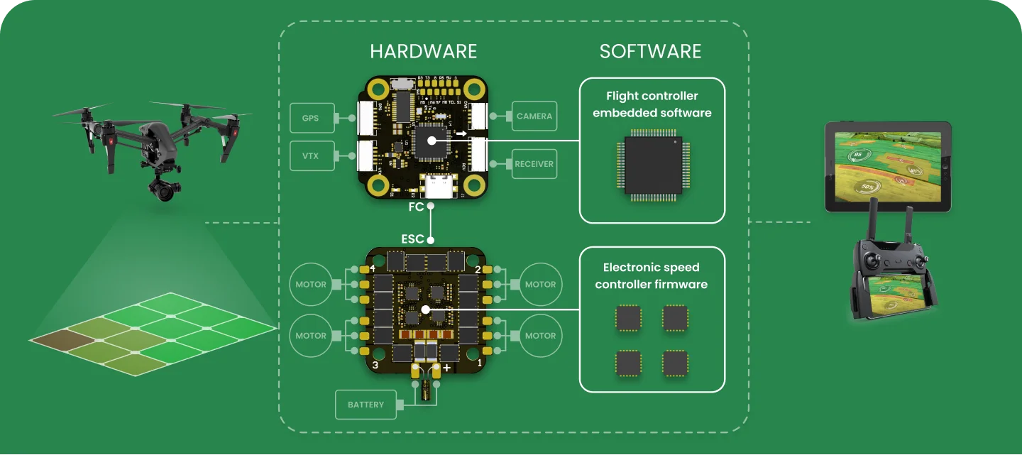
Select the microcontrollers, power-supply components, input/output interfaces and other parts for the flight controller and the ESC.
PCB layout and production files
Lay out both boards with attention to component placement, signal integrity, layer stack-up and electrical and thermal requirements, and prepare Gerber files, bills of materials and assembly drawings for the EMS vendor.
Bring-up and revision
Bring up the first board iterations in-house, load firmware to exercise them, and issue updated production files for a second revision.
Worked with
Betaflight and BLHeli
The flight controller targets Betaflight and the ESC targets BLHeli. Project silicon includes the STM32F405 and the Silicon Labs EFM8 Busy Bee.
Flight-controller interfaces
The specification fixed the number of communication ports and the supported receiver characteristics; the flight controller and ESC connect as one stack that drives the motors.
EMS vendor
Production files, the bill of materials and assembly drawings were handed to the manufacturer, which built and tested the boards against the specification.
Product constraints
What made the engineering difficult
- 01
High-current ESC design
The ESC handles currents of up to 55 A per channel, so bench work needed a dedicated power supply with current limiting before boards could be tested safely.
- 02
Debugging power electronics
Hardware debugging of the ESC was difficult. The team developed debugging protocols specifically for the ESC design.
- 03
Custom boards on open-source firmware
The boards had to match a flight stack of their own design while remaining compatible with the most widely used open-source flight and ESC firmware.
- 04
Starting from nothing
With only a concept to start from, requirements, specification, schematics and layout had to be defined in sequence before anything could be manufactured.
Engineering judgement
Decisions that shaped the product
Prove the risky parts first
Prototype non-trivial components, such as the ESC MOSFETs under stress, before freezing the schematic.
Design for existing firmware
Make the boards compatible with Betaflight and BLHeli instead of writing flight and motor-control firmware from scratch.
Write the requirements down before drawing
Use a functional requirements document followed by a technical specification so that board-level choices trace back to stated product requirements.
Check before first power-on
Check for shorts, verify voltages and watch for overheating components before powering new boards, then load firmware to test function.
Treat bring-up as iterative
Plan for several rounds of testing and changes; feed results into updated production files for the next board revision.
Delivered product capability
What the product can do
- 01
Flight-controller design
Schematic and multi-layer PCB layout for the flight controller, specified for the required ports, receiver support, MCU and flash.
- 02
ESC design
Schematic and PCB layout for the electronic speed controller, including the high-current power stage.
- 03
Manufacturing package
Gerber files, bills of materials and assembly drawings for both boards, used by the EMS vendor to build them.
- 04
Bring-up and test reports
In-house bring-up of the first board iterations with firmware loaded, documented in test reports.
- 05
Second revision
Updated production files based on bring-up results, sent to the manufacturer for the second board revision.
- 06
Engineering documentation
Functional requirements document and technical specification for the flight stack.
Product change
What changed for the product team
The client moved from a concept to manufactured flight-controller and ESC boards that had been brought up and tested, backed by requirements, a technical specification, test reports and updated production files for a second revision.
For a drone team that wants its own flight electronics rather than an off-the-shelf stack, the case shows the path from requirements to schematics, layout, contract manufacturing and iterative bring-up, with compatibility with open-source flight firmware kept as a design constraint throughout.
- Flight-controller and ESC boards were designed, built by an EMS vendor and brought up with firmware loaded for functional testing.
- Bring-up results fed into updated production files for a second board revision.
Product evidence
A closer look at the product
Technology, in context
Altium Designer · C/C++ · Assembly language · STM32F405 · Silicon Labs EFM8 Busy Bee · Betaflight · BLHeli
A comparable product problem?
Drone flight-stack electronics
Bring the product context, the system that already exists and the engineering decision you need to make.